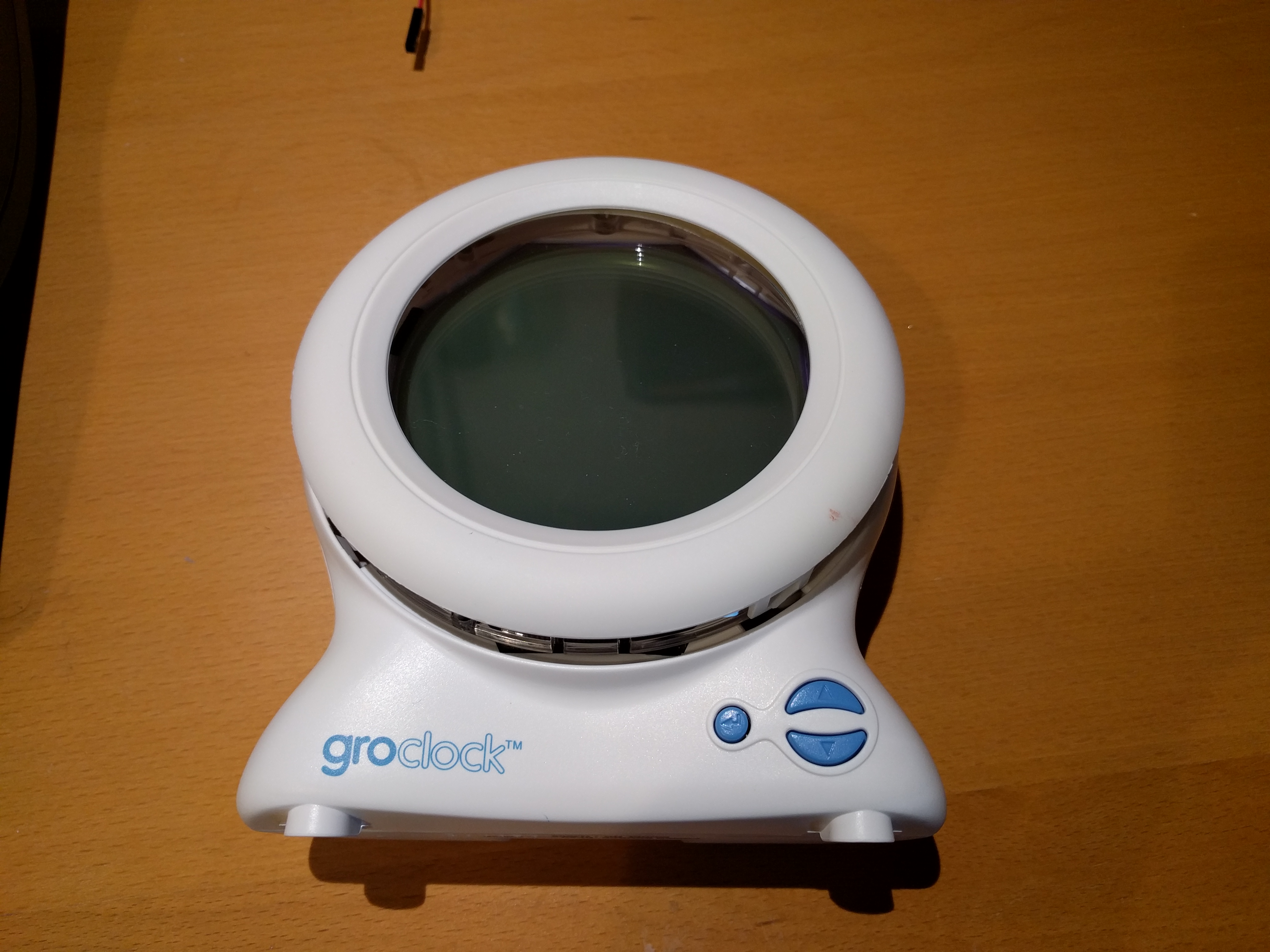
Gro-clock Teardown
The Gro-clock is a children's sleep aid, intended to help young kids stay in bed until it's time to get up. Unfortunately it displays an intense blue light from its clockface during the "stay in bed" phase, which is quite bright even on the lowest setting. Research has shown that blue light supresses melatonin and disrupts sleep; this doesn't seem like a good idea in a product that's supposed to be helping children to sleep.
I decided to take mine to bits to see if I could easily hack it to display red light at night (red is proven to be the least disuptive colour to melatonin). My hope was that the LEDs lighting the LCD would be RGB tricolour (the clock face goes yellow when it's time to get up, so there's obviously at least two LEDs in there) and I could just swap the wiring around (and probably add a resistor on the red LED as they have a lower forward voltage than blue LEDs).
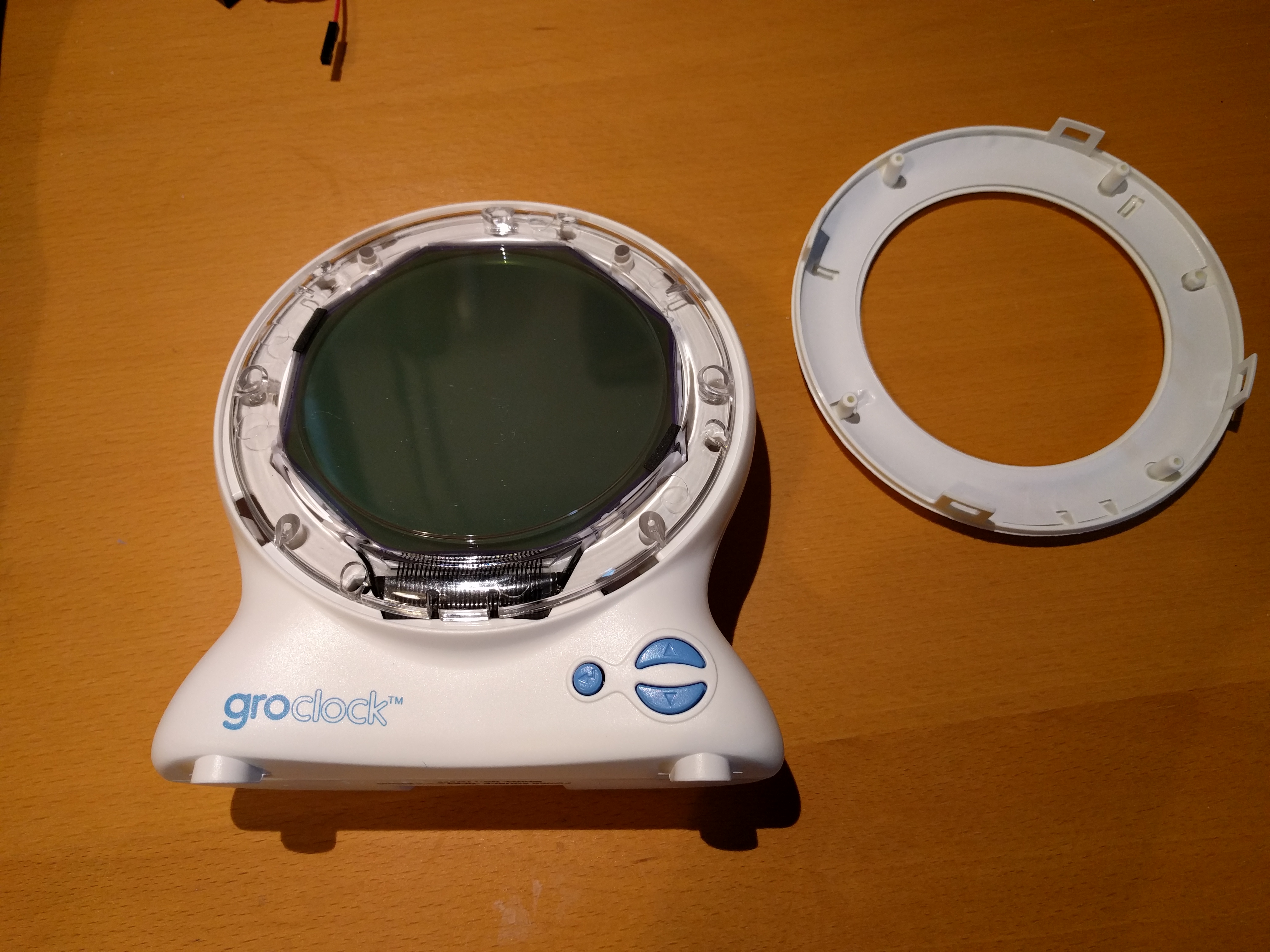
The first step in opening is to pull off the bit of plastic surrounding the clock face. I managed this with my fingernails; a plastic spudger would probably be ideal.
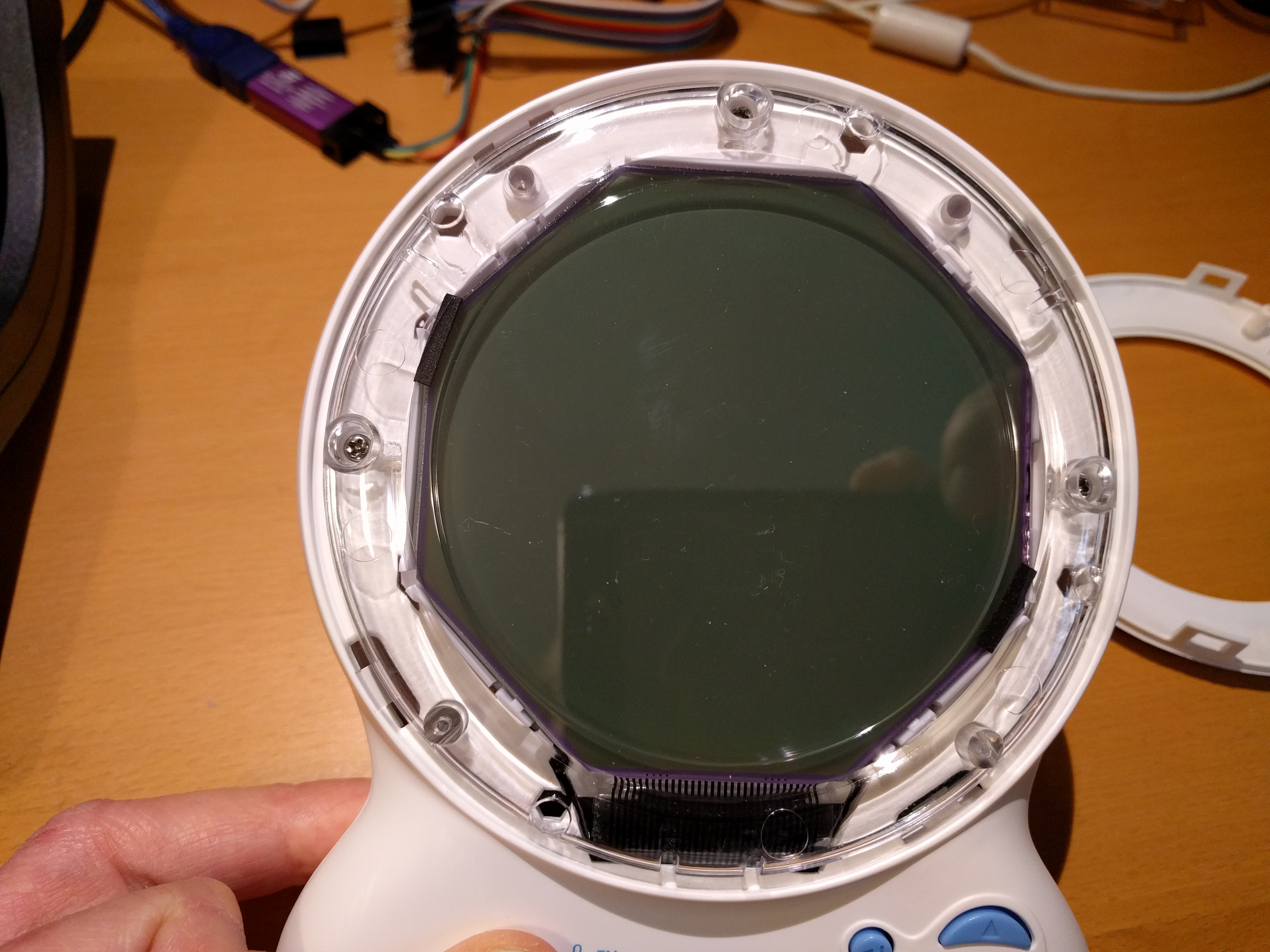
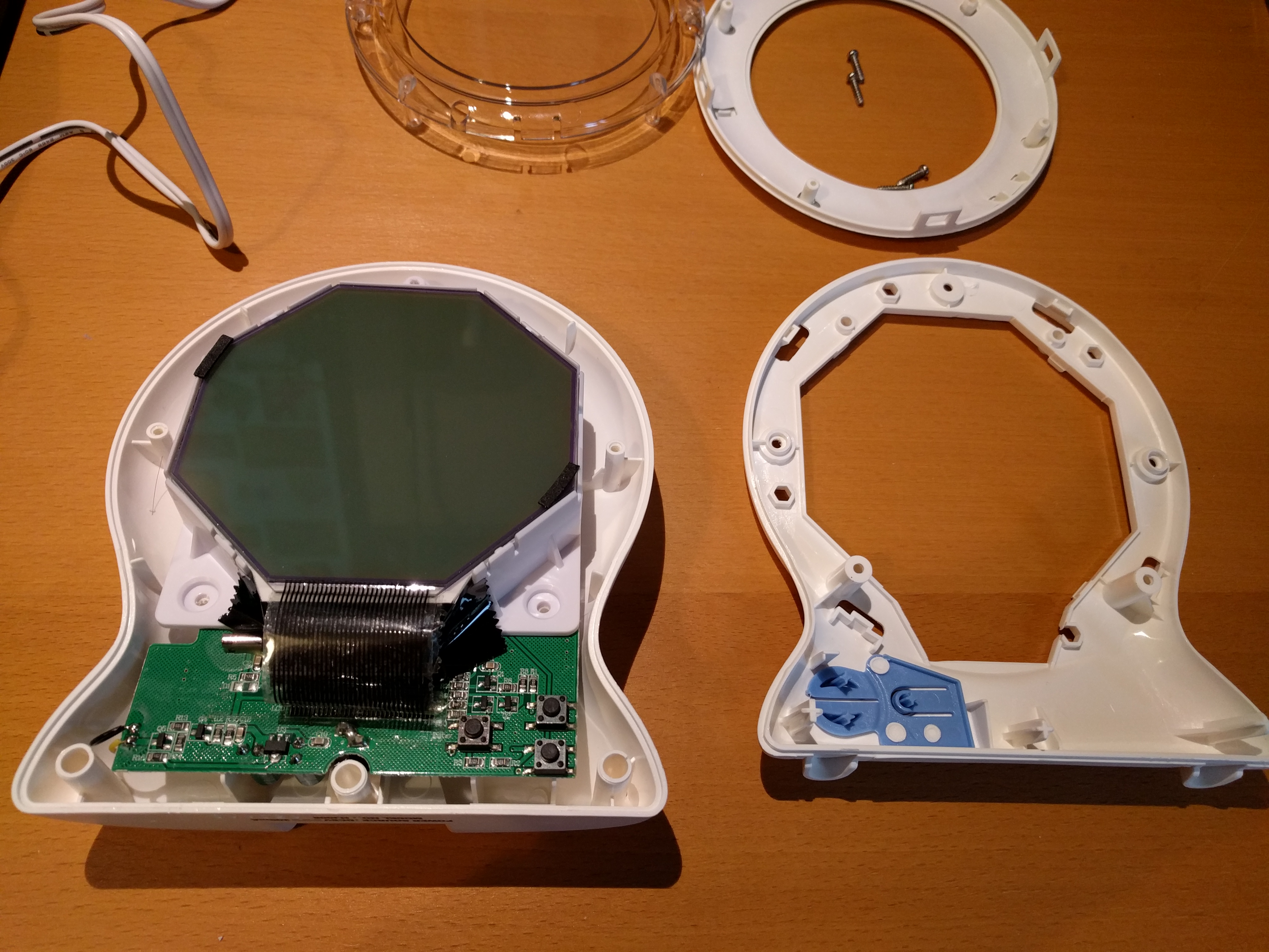
Lifting this surround off reveals an octagonal LCD connected with flexible plastic ribbon cable:
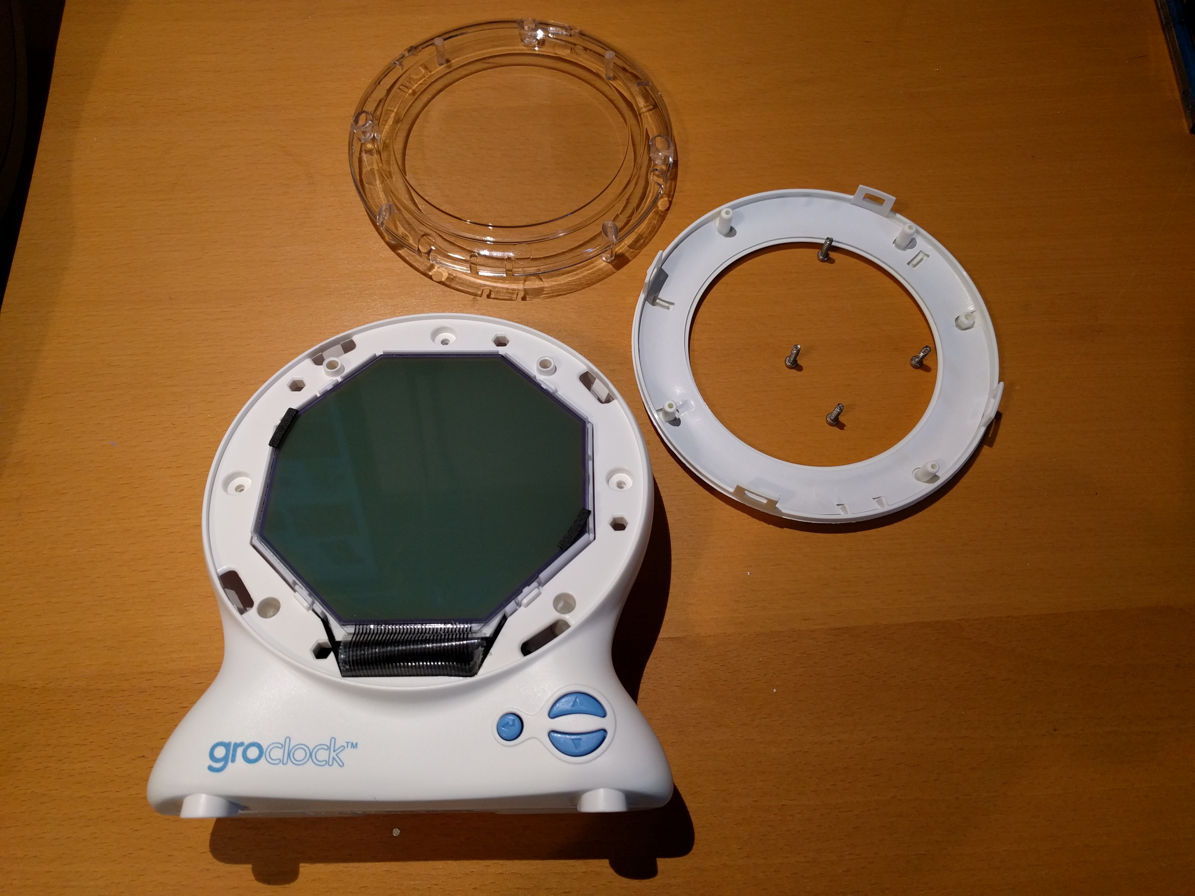
There is a transparent piece of plastic holding the LCD in place with Phillips screws:
Once the screws are removed, the clear plastic ring lifts off. There are two more screws adjacent to the bottom of the LCD holding the front part of the clock in place:
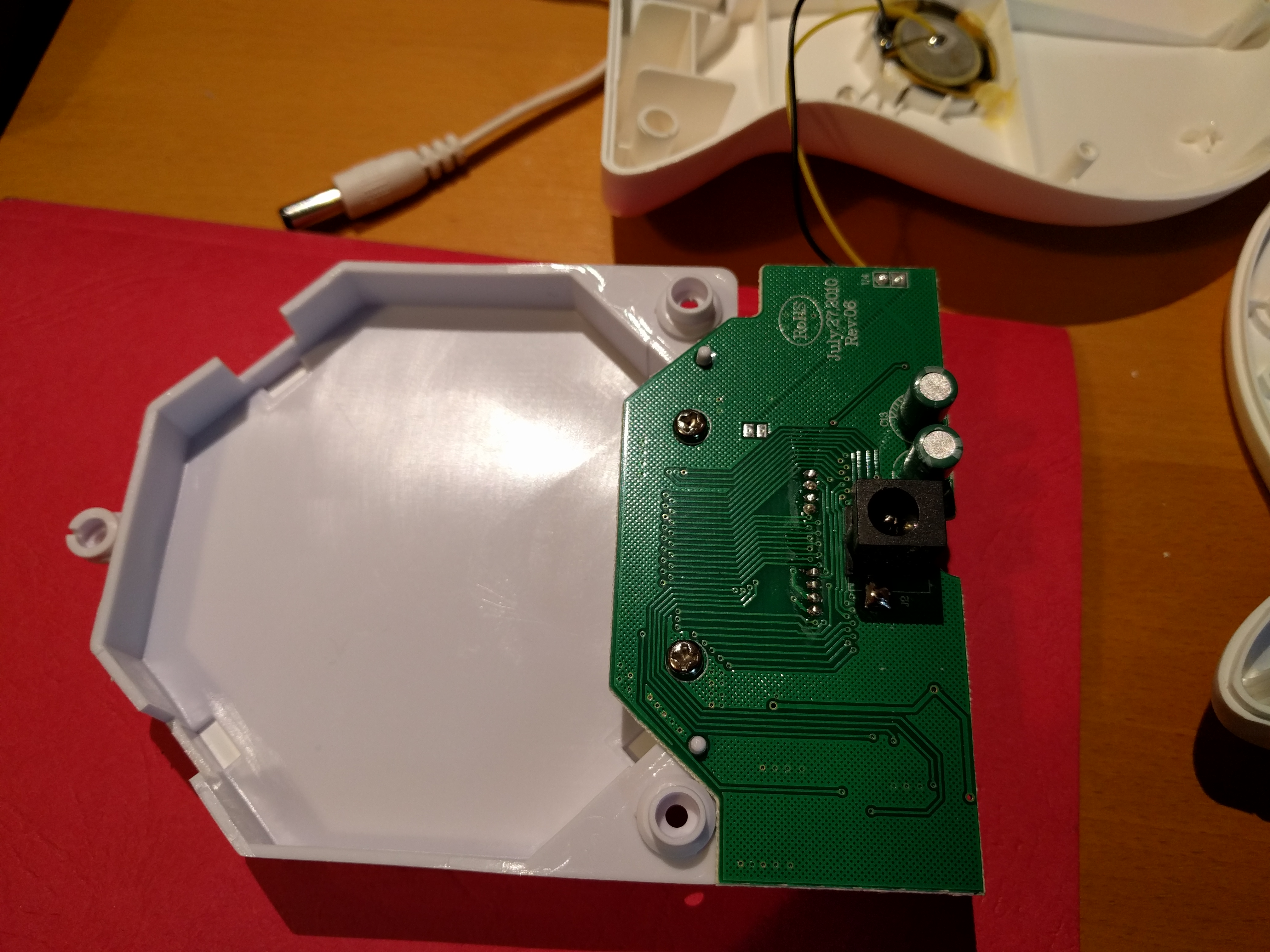
Removing the front of the clock is slightly tricky. The base needs to be prised apart. I used a small screwdriver, a plastic spudger would again be a better bet. The top part separates fairly easily. Lifting it off reveals the PCB and two more screws (already removed in this photo):
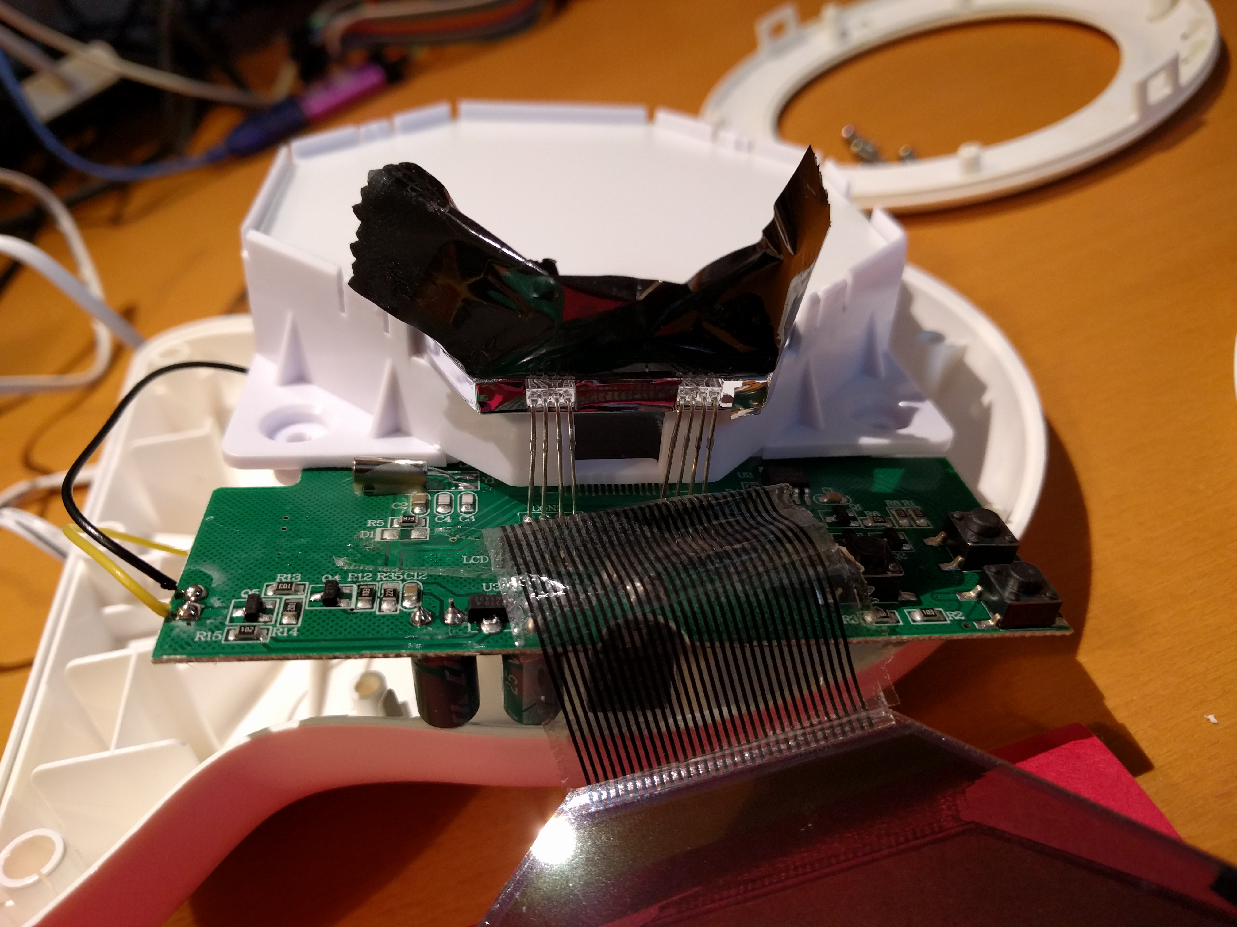
Once the screws are out, the back of the clock can be removed. Careful as it's attached to a piezo sounder by two wires:
Looking up at the base of the LCD, you can see two edge-lighting LEDs. They have 4 legs so they should have 3 LED elements inside - I was hoping they'd be RGB, however testing revealed they're yellow / green / blue - an odd combination (I don't have a photo of them lit unfortunately):
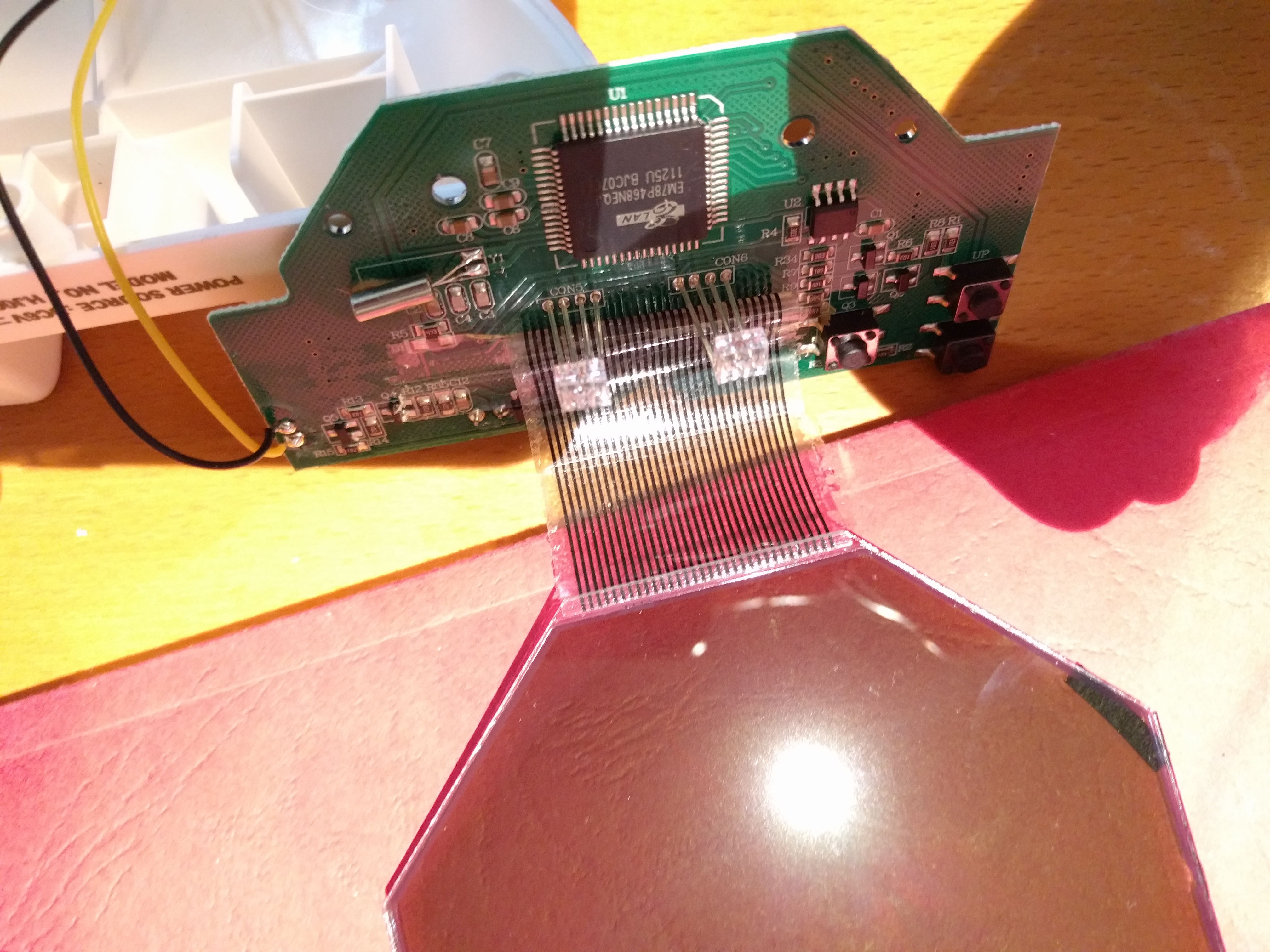
Next step was to look at the PCB. The interesting components are on the underside:
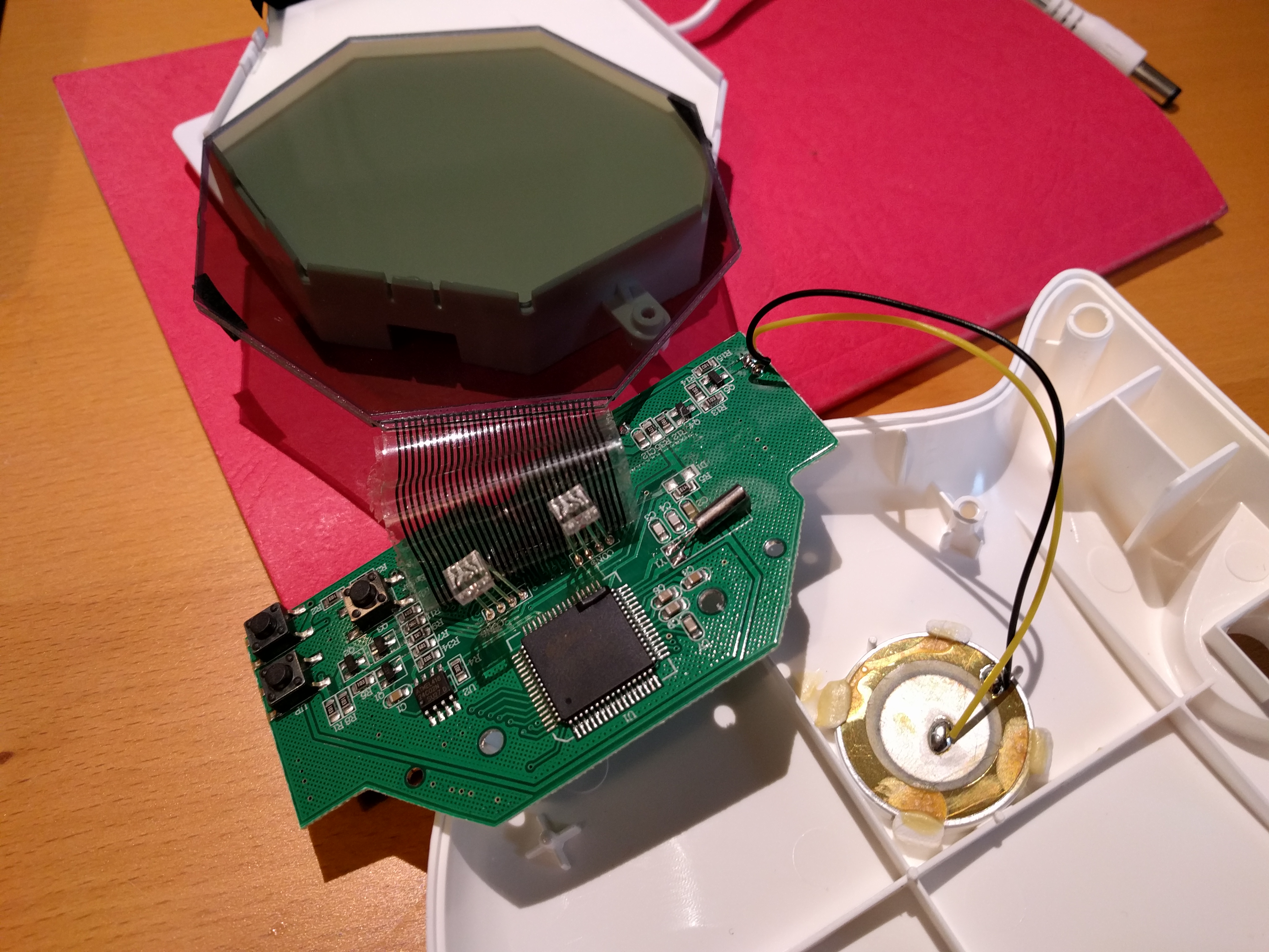
The large IC is an Elan EM78P468NEQ 8-Bit Microcontroller. Sadly, the datasheet reveals that "[t]he series has an on-chip 4K x 13-bit Electrical One Time Programmable Read Only Memory (OTP-ROM)", so there's no way to reprogram:
The other IC is an Atmel 24c02n Two-wire Serial EEPROM, presumably for holding settings as a quick search of the Elan MCU datasheet didn't reveal any onboard EEPROM.
Given that the LEDs don't have a red element, and I didn't have any RGB LEDs handy, I put it all back together again without making any changes. Disconnecting the blue LEDs altogether may be the best bet, so it's dark during the "sleep" phase and goes yellow when it's time to get up.